Fire Flow Alternative
The Fire Flow Alternative contains the input data required to perform a fire flow analysis. This data includes the set of junction nodes for which fire flow results are needed, the set of default values for all junctions included in the fire flow set, and a record for each junction node in the fire flow set.
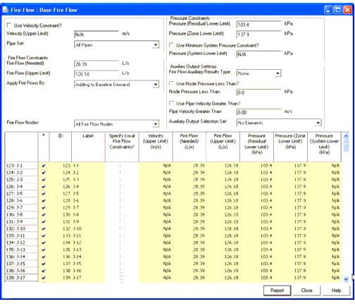
The Fire Flow Alternative window is divided into sections which contain different fields to create the fire flow. These fields include:
Use Velocity Constraint?: If set to true, then a velocity constraint can be specified for the node.
Velocity (Upper Limit): Specifies the maximum velocity allowed in the associated set of pipes when drawing out fire flow from the selected node.
Pipe Set: The set of pipes associated with the current node where velocities are tested during a fire flow analysis.
Fire Flow (Needed): Flow rate required at the junction to meet fire flow demands. This value will be added to the junction's baseline demand or it will replace the junction's baseline demand, depending on the default setting for applying fire flows.
Fire Flow (Upper Limit): Maximum allowable fire flow that can occur at a withdrawal location. This value will prevent the software from computing unrealistically high fire flows at locations such as primary system mains, which have large diameters and high service pressures. This value will be added to the junction's baseline demand or it will replace the junction's baseline demand, depending on the default setting for applying fire flows.
Apply Fire Flows By: There are two methods for applying fire flow demands. The fire flow demand can be added to the junction's baseline demand, or it can completely replace the junction's baseline demand. The junction's baseline demand is defined by the Demand Alternative selected for use in the Scenario along with the fire flow alternative.
Fire Flow Nodes: A selection set that defines the fire flow nodes to be subject to a fire flow analysis. The selection set must be a concrete selection set (not query based) and must include the junctions and hydrants that need to be analyzed. Any non-junction and hydrant elements in the selection set are ignored.
Pressure (Residual Lower Limit): Minimum residual pressure to occur at the junction node. The program determines the amount of fire flow available such that the residual pressure at the junction node does not fall below this target pressure.
Pressure (Zone Lower Limit): Minimum pressure to occur at all junction nodes within a zone. The model determines the available fire flow such that the minimum zone pressures do not fall below this target pressure. Each junction has a zone associated with it, which can be located in the junction's input data. If you do not want a junction node to be analyzed as part of another junction node's fire flow analysis, move it to another zone.
Use Minimum Pressure Zone Constraint?: Check whether a minimum pressure is to be maintained throughout the entire pipe system.
Pressure System Lower Limit: Minimum pressure allowed at any junction in the entire system as a result of the fire flow withdrawal. If the pressure at a node anywhere in the system falls below this constraint while withdrawing fire flow, fire flow will not be satisfied.
Fire Flow Auxiliary Results Type: This setting controls whether the fire flow analysis will save "auxiliary results" (a snap shot result set of the fire flow analysis hydraulic conditions) for no fire flow nodes, just the failing fire flow nodes, if any, or all fire flow nodes. For every fire flow node that attracts auxiliary results a separate result set (file) is created. When enabling this setting be conscious of the number of fire flow nodes in your system and the potential disk space requirement. Enabling this option also will slow down the fire flow analysis due to the need to create the additional results sets. Note: The base result set includes hydraulic results for the actual fire flow node and also for the pipes that connect to the fire flow node. The results stored are for the hydraulic conditions that are experienced during the actual fire flow analysis (i.e., under fire flow loading). No other hydraulic results are stored unless the auxiliary result set is "extended" by other options listed below.
Use Extended Auxiliary output by Node Pressure Less Than: Defines whether to include in the stored fire flow auxiliary results, results for nodes that fall below a defined pressure value. Such nodes might indicate low pressure problems under the fire flow conditions.
Node Pressure Less Than?: Specifies the number.
Use Pipe Velocty greater Than: Defines whether to include in the stored fire flow auxiliary results, results for pipes that exceed a defined velocity value. Such pipes might indicate bottle necks in the system under the fire flow conditions.
Pipe Velocity Greater Than: Specifies the number.
Auxiliary Output Selection Set: This selection set is used to force any particular elements of interest (e.g., pumps, tanks) into a fire flow node's auxiliary result set, irrespective of the hydraulic result at that location. Said another way this option defines which elements to always include in the fire flow auxiliary result set for each fire flow node that has auxiliary results.
Fire Flow System Data
Each fire flow alternative has a set of default parameters that are applied to each junction in the fire flow set. When a default value is modified, you will be prompted to decide if the junction records that have been modified from the default should be updated to reflect the new default value.
The table consists of the following columns:
ID: Displays the unique identifier for each element in the alternative.
Label: Displays the label for each element in the alternative.
Specify Local Fire Flow Constraints?: Select this check box to allow input different from the global values. When you select this check box, the fields in that row turn from yellow (read-only) to white (editable).
Velocity (Upper Limit): Specify the maximum velocity allowed in the associated set of pipes when drawing out fire flow from the selected node.
Fire Flow (Needed): Flow rate required at a fire flow junction to satisfy demands.
Fire Flow (Upper Limit): Maximum allowable fire flow that can occur at a withdrawal location. It will prevent the software from computing unrealistically high fire flows at locations such as primary system mains, which have large diameters and high service pressures.
Pressure (Residual Lower Limit): Minimum residual pressure to occur at the junction node. The program determines the amount of fire flow available such that the residual pressure at the junction node does not fall below this target pressure.
Pressure (Zone Lower Limit): Minimum pressure to occur at all junction nodes within a zone. The model determines the available fire flow such that the minimum zone pressures do not fall below this target pressure. Each junction has a zone associated with it, which can be located in the junction's input data. If you do not want a junction node to be analyzed as part of another junction node's fire flow analysis, move it to another zone.
Pressure (System Lower Limit): Minimum pressure to occur at all junction nodes within the system.